von duprin 98 99 installation instructions

The Von Duprin 98/99 Series exit devices are reliable, durable, and designed for heavy-duty commercial applications. Known for their safety and functionality, these devices are widely used in offices, schools, and public buildings. Their robust construction ensures long-lasting performance, making them a popular choice for securing doors while meeting fire and safety regulations.
1.1 Overview of the 98/99 Series
The Von Duprin 98/99 Series exit devices are engineered for heavy-duty use, offering reliability and durability in high-traffic environments. Available in rim and surface vertical rod configurations, these devices are suitable for single or double doors. The series includes fire-rated options, ensuring compliance with safety standards. Their robust design and versatile installation options make them ideal for commercial applications, providing secure and efficient door operation.
1.2 Key Features of the 98/99 Rim Exit Devices
The Von Duprin 98/99 Rim Exit Devices feature a durable, heavy-duty design with a robust mechanism for reliable operation. They include fire-rated options (98-F/99-F) for compliance with safety standards. These devices offer smooth functionality, with features like solenoid wiring for electrification and optional classroom security indicators. The 98/99 series also supports remote undogging and monitoring kits, enhancing security and control. Their versatile design accommodates various door configurations and applications.
Types of Von Duprin 98/99 Exit Devices
The Von Duprin 98/99 Series includes rim exit devices, fire-rated options (98-F/99-F), and surface vertical rod exit devices (98/9927 Series), offering versatile solutions for different applications.
2.1 Rim Exit Devices (98/99 Series)
The Von Duprin 98/99 Series Rim Exit Devices are designed for durability and functionality. They are suitable for heavy-duty commercial use, offering smooth operation and reliability. These devices are available in various configurations, including non-fire-rated and fire-rated options, ensuring compliance with safety standards. They are easy to install and maintain, making them ideal for high-traffic environments.
2.2 Fire-Rated Devices (98-F/99-F Series)
The Von Duprin 98-F/99-F Series Fire-Rated Exit Devices are engineered to meet stringent fire safety standards. These devices are designed for use on fire-rated doors, ensuring reliable operation during emergencies. They include features like dogging options and are available in rim and surface vertical rod configurations, providing flexibility for various door setups while maintaining compliance with fire codes and regulations.
2.3 Surface Vertical Rod Exit Devices (98/9927 Series)
The Von Duprin 98/9927 Series offers surface vertical rod exit devices, ideal for heavy-duty applications requiring a robust panic exit solution. These devices feature a visible vertical rod and are suitable for high-traffic areas. They are available in fire-rated options (98/9927-F), ensuring compliance with safety standards while providing reliable functionality for secure and efficient door operation in various commercial environments.
Pre-Installation Requirements
Before installing Von Duprin 98/99 exit devices, ensure proper tools, materials, and door preparation. Review the screw chart and hardware requirements for accurate installation and functionality.
3.1 Tools and Materials Needed
Essential tools include a drill, screwdrivers, measuring tape, level, and wrenches. Materials required are fasteners, strike plates, and door preparation hardware. Refer to the screw chart for specific screw types and sizes. Ensure all components are compatible with the door material (wood or metal) for secure installation. Proper tools and materials ensure a precise and durable setup, avoiding installation errors.
3.2 Door Preparation and Measurements
Ensure the door is properly prepared by marking center lines for the exit device and strike. Measure and align components accurately, ensuring compliance with height requirements (e.g., 101.1 cm from the floor). For double doors, verify mullion and strike placement. Proper door preparation and precise measurements are critical for correct installation and optimal functionality of the exit device.
3.3 Understanding the Screw Chart and Hardware Requirements
Refer to the screw chart to identify correct screw types and sizes for installation. Metal doors require specific screws, such as 10-24, to ensure secure mounting. Proper hardware selection is crucial for durability and functionality. Use the chart to match screws with door material and thickness, ensuring all components are properly fastened. This step prevents installation errors and guarantees reliable operation of the exit device.

Installation Steps for Von Duprin 98/99 Rim Exit Devices
Mount the exit device, align and install the strike, then secure it to the door. Follow step-by-step instructions for proper installation and functionality.
4.1 Mounting the Exit Device
Begin by preparing the door and marking the center line for proper alignment. Drill holes for screws as specified in the screw chart. Insert the screws into the predrilled holes and align the exit device with the center line. Tighten the screws securely to ensure the device is firmly mounted. Follow the instructions carefully to avoid misalignment and ensure proper functionality.
4.2 Aligning and Installing the Strike
Align the strike center line with the exit device’s latch bolt. Mark the screw holes on the door frame or mullion. Drill pilot holes if necessary and secure the strike using the specified screws from the screw chart. Ensure the strike is flush and properly aligned to guarantee smooth operation of the exit device. Double-check the alignment before final tightening.
4.3 Securing the Device to the Door
Ensure the exit device is properly aligned with the strike. Use the screw chart to select the correct screws for your door material. Drill pilot holes to avoid splitting the door material, especially for wooden doors. Insert screws and tighten them firmly but avoid over-tightening. Double-check alignment with the strike center line for smooth operation. For double doors, align with the mullion and existing markings. Inspect the door and device for any damage before securing.
Electrical Preparation and Wiring
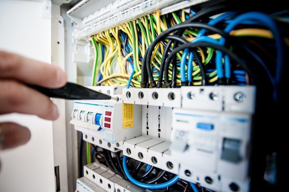
Ensure the solenoid is correctly wired to the PS873 logic board. Review wiring diagrams and instructions before starting. Install the mortise cylinder during electrical setup for easier access and proper alignment. Follow manufacturer guidelines for remote undogging and monitoring kits to ensure seamless functionality and safety compliance.
5.1 Solenoid Wiring and Logic Board Connection
Connect the solenoid to the PS873 logic board, ensuring proper wiring according to the provided diagrams. For 871-2 logic boards, refer to Von Duprin instructions (941352). Secure all connections tightly to avoid electrical issues. The solenoid draws a 16A inrush current, so verify power supply compatibility. Follow step-by-step instructions to ensure correct wiring and functionality. Consult the manual for specific logic board configurations and troubleshooting tips.
5.2 Installing the Mortise Cylinder
Ensure the mortise cylinder is installed before proceeding with electrical connections for easier access. Choose a 1 1/4 or 1 3/8 cylinder, aligning it with the device’s centerline. Secure the cylinder using screws provided, tightening firmly. Double-check the cylinder’s orientation to match door handing. Apply supplied labels above and below the cylinder if using a Classroom Security Indicator for clear operation indication.
5.3 Remote Undogging (RU) and Monitoring (RM) Kits
Remote Undogging (RU) and Monitoring (RM) kits enable remote control and monitoring of exit devices. These kits are compatible with 98/99 and 33A/35A series devices. Install the RU kit for remote undogging functionality and the RM kit for monitoring door status. A PS873 logic board is required for solenoid wiring. Refer to specific instructions for wiring diagrams and ensure proper installation for reliable operation. Patent numbers apply as specified in the manual.
Special Considerations
Special considerations include wind-rated hurricane devices (HH option) and classroom security indicators. Through bolts are required for HH devices to ensure durability and proper functionality. Always follow instructions for optimal performance and compliance.
6.1 Wind and Impact-Rated Hurricane Devices (HH Option)
The HH option for Von Duprin 98/99 Series exit devices is designed to withstand extreme weather conditions. These devices are wind and impact-rated, ensuring reliability in hurricane-prone areas. Through bolts are required for installation to enhance durability. Proper alignment and secure fastening are critical to maintain the device’s integrity and functionality under harsh environmental stress. Always refer to specific installation guidelines for HH models to ensure compliance with safety standards and optimal performance.
6.2 Classroom Security Indicator Installation
The Classroom Security Indicator is an optional feature for Von Duprin 98/99 Series exit devices. It provides visual confirmation of the door’s locking status, enhancing classroom safety. To install, apply the supplied labels above and below the mortise cylinder, ensuring alignment with the door’s handing. Proper installation ensures clear visibility of the indicator, which is critical for secure classroom environments. Follow specific guidelines for accurate placement and functionality.
6.3 Through Bolt Requirements for HH Devices
For Von Duprin 98/99 Series HH (Hurricane) devices, through bolts are mandatory to ensure structural integrity and resistance to wind and impact. These bolts must be installed as specified in the instructions, typically through the door and frame. Properly securing the device with through bolts is critical to maintain functionality and safety in extreme weather conditions, adhering to all relevant building codes and standards.

Retrofit Kit Installation
Retrofit kits for Von Duprin 98/99 devices allow upgrading existing hardware with modern features like remote undogging (RU) and monitoring (RM). Follow step-by-step instructions for seamless installation.
7.1 Retrofitting Remote Undogging (RU) Kits
RU kits enable remote control of exit devices, enhancing security and convenience. Retrofitting involves replacing existing components with RU-compatible parts. Ensure proper wiring to the logic board and test functionality post-installation. Follow detailed instructions to avoid errors and ensure seamless integration with existing systems for reliable operation.
7.2 Retrofitting Remote Monitoring (RM) Kits
Retrofitting RM kits allows real-time monitoring of exit device status. Install sensors and connect wiring to the logic board, ensuring compatibility with existing systems. Follow manufacturer instructions to avoid errors. Test functionality post-installation to confirm proper operation. Professional installation is recommended for optimal performance and reliability.

Troubleshooting Common Issues
Address solenoid inrush current and wiring issues by checking connections. Adjust strike alignment for proper latch bolt engagement. Consult manuals or seek professional assistance for complex problems.
8.1 Solenoid Inrush Current and Wiring Issues
Solenoid inrush current can cause electrical spikes, potentially damaging circuits. Ensure proper wiring connections and use a PS873 logic board to manage power effectively. Verify wiring diagrams for accuracy and consult manuals if issues persist. Incorrect wiring may lead to device malfunction, so double-check connections before powering up the system. Regular inspections can prevent such issues from arising.
8.2 Strike Alignment and Adjustment
Improper strike alignment is a common issue that can prevent smooth operation. Ensure the strike is correctly aligned with the latch bolt, using the centerline marks as a guide. Adjust the strike screws to achieve proper alignment, and verify that the latch bolt engages securely. If misalignment persists, consult the installation instructions for further adjustment or shimming requirements to ensure optimal functionality and longevity of the device.

Maintenance and Upkeep
Regular inspection and lubrication of moving parts are essential for optimal functionality; Ensure all components are clean, well-lubricated, and properly adjusted to maintain performance and longevity.
9.1 Regular Inspection of Exit Devices
Regularly inspect all mechanical components, such as the touchpad, pushbar, and strike, to ensure proper functionality. Clean and lubricate moving parts to prevent wear and tear. Check for any signs of damage or misalignment, and address issues promptly to maintain safety and efficiency. Refer to the maintenance manual for detailed inspection procedures and recommended schedules.
9.2 Lubrication and Adjustment of Moving Parts
Apply a light coat of silicon-based lubricant to hinge pins and moving components to ensure smooth operation. Adjust the exit device’s alignment and tension as needed, following the manufacturer’s instructions. Regular lubrication prevents wear and tear, while proper adjustments maintain optimal functionality and safety compliance. Always refer to the maintenance manual for specific guidance on lubrication intervals and adjustment techniques.
This concludes the comprehensive guide on Von Duprin 98/99 exit devices, ensuring safe and reliable operation through proper installation and maintenance.
10.1 Final Checklist for Successful Installation
- Ensure strike alignment is precise for smooth operation.
- Verify device is securely fastened to the door.
- Confirm solenoid wiring matches the logic board connections.
- Check mortise cylinder installation for proper function.
- Inspect through bolts for HH devices if applicable.
- Test exit device functionality and remote features.
- Review all steps in the manual to ensure compliance.